
Contours are used as a standardized method to generally predict the coverage area of a broadcast station as well as the areas where a station could cause interference to other stations. The calculations are based on whether a signal can be received at the field strength indicated on 50% of the receivers, 50% of the time. This is known as the F(50, 50) curves. This curve measurement is used mainly to determine coverage of FM radio and analog television. The F(50, 10) curve is a similar theory, except that it is 50% of the receivers, 10% of the time. F(50, 10) is used to determine interference. Digital television also uses an F(50, 90) curve as signal strength for TV is more demanding.
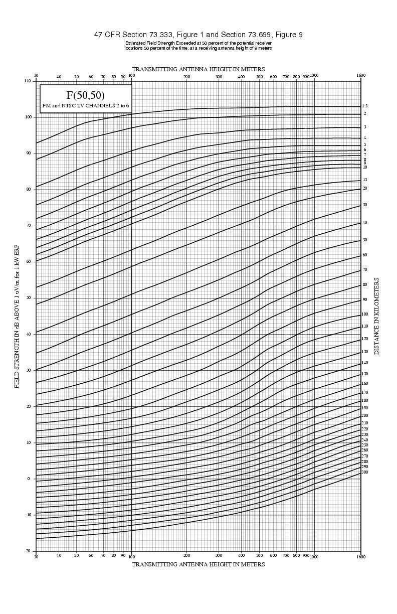
The curves that are used by the FCC are developed on a chart. In the old days, engineers would have to determine the value of the curve at the X and Y coordinates on the chart. These coordinates were based on the height above average terrain and the field strength based on 1 kW ERP. The curves are based on the distance from the transmitter. An example of the F(50, 50) chart is shown below.
Fortunately, in this day of computers, it is not necessary to use the charts as there are computer programs to solve these formulas. The FCC developed charts are also used in Canada and Mexico. In the rest of the world, a different set of charts were developed by the International Telecommunications Union as a world standard.
Using the method of contour overlap, you have to demonstrate that the F(50, 10) interfering contour of the undesired facility does not overlap the F(50, 50) contour of the desired facility. The ratio that is used varies by the adjacency of the channel relationship between the two stations and is referred to as the Desired to Undesired (D/U) ratio (some may call it U/D).
| Relationship | U/D Ratio | Desired Field Strength F(50,50) | Undesired Field Strength F(50,10) |
|---|---|---|---|
| Co-channel | -20 | 60 dBu | 40 dBu |
| First-adjacent (+/- 200 kHz) | -4 | 60 dBu | 54 dBu |
| Second/Third adjacent (+/- 400 or 600 kHz) | 40 | 60 dBu | 100 dBu |
For allocation purposes, the FCC and Mexico use different desired and undesired field strengths for certain classes of stations. For example a Class B FM station in the US and Mexico would have a 54 dBu desired field strength and a 34 dBu undesired field strength on co-channel. Canada does have some variances in their D/U ratios based on station class.
The F(50, 50) contour is also referred to as the protected contour or the service contour. The (50, 10) contour is also referred to as the interfering contour.
In the United States, the following rules apply for contour overlap:
- For reserved band (88.1~91.9) FM stations as well as commercial band FM stations seeking short-spacing under §73.215 of the rules, the interfering contour of the proposed station can't overlap the protected contour of the incumbent station. Likewise, the protected contour of the proposed station cannot overlap the interfering contour of the incumbent station. Therefore, there must be protections both ways.
- For FM translators, the interfering contour of the proposed station can't overlap the protected contour of the proposed station. Unlike full-service FM, the proposed station's service contour can be inside the interfering contour of the incumbent station. In this case, the proposed translator is accepting the potenial of interference being caused by the operation of the existing incumbent station.
- Full service FM uses distance separation minimums that are based on the longer distance needed to protect both stations both ways if both stations were at the maximum facilities for their service class and on flat earth without terrain.
- LPFM uses distance separation minimums that are based on the distance necessary to make prevent the interfering contour of an LPFM station to overlap into the protected contour of the incumbent station. Again, this is based on maximum facilities for each service class and on flat-earth. For incumbent stations that are full-service domestic FM stations, an additional 20 kilometers is added to the maximum service contour thus providing a "buffer zone" between the interfering contour of the LPFM station and the protected contour of the full service station.
To measure the contours, engineers, consultants will normally use computer software that measures the Height Above Average Terrain (HAAT) at 50 equally-spaced points located between 2 and 10 miles from the transmitting point along each radial (either 72 or 360). The chart shown above will be used to determine the distance from the transmitter site to that specified contour. For example, for a transmitter operating at 100 watts ERP and is at 30 meters above average terrain, the 60 dBu protected contour will extend to 5.6 kilometers.
One important thing to remember about contours:
They are used mainly for allocation purposes and are not a true depiction of actual coverage by a specific facility. The way that the manual charts are designed, there is no capability to measure a contour of less than 30 meters HAAT. Therefore, any antenna that is located under 30 meters HAAT is considered 30 meters HAAT for allocation purposes. This is the reason why many stations, especially LPFM stations can't achieve a usable signal within their 60 dBu service/protected contour. Contours can be deceiving.
REC/FCC Curves Tool - use this to determine the distance to a particular contour.
Interference in the FM Band - Vernier, Doug; V-Soft Communications (2012)
Planning Standards for terrestrial FM sound broadcasting at VHF ITU-R BS.412-9 (12/1998) - ITU standard for outside of the USA, Mexico and Canada
